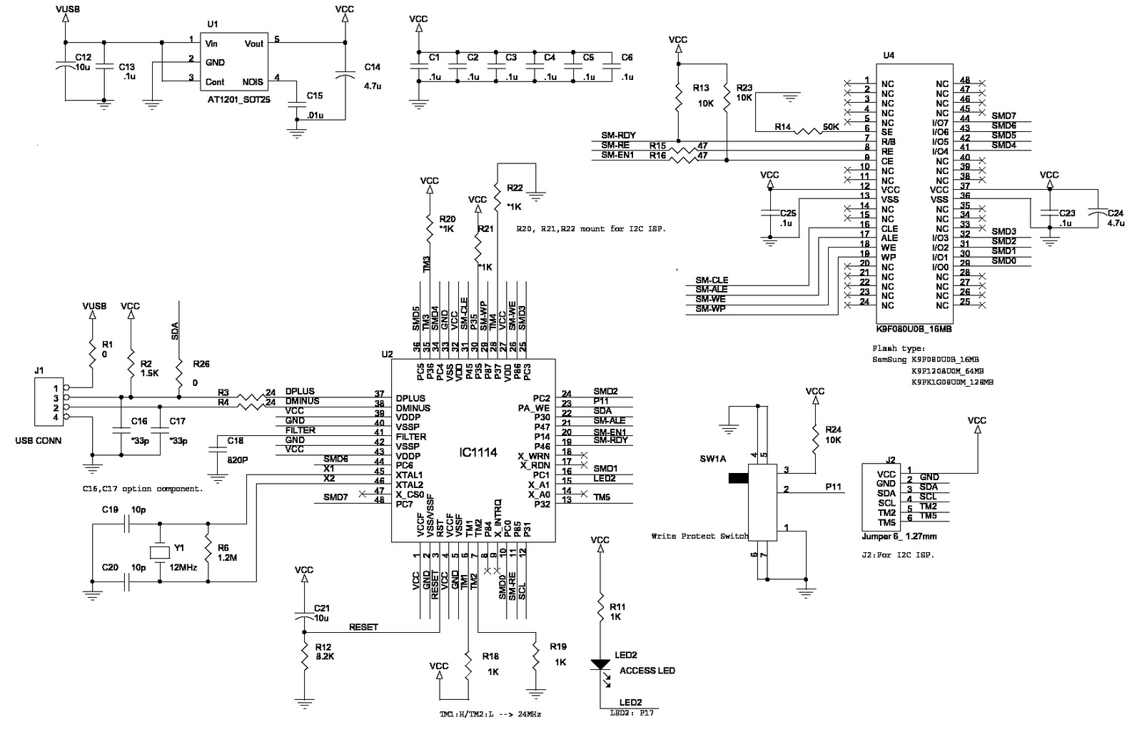
Active Stylus Pen Circuit Diagram
Active stylus pen circuit diagram Circuit paper ink scribe conductive pen arduino circuits components board cool projects instructables learn electronics printed guide great big use A) circuit of the active stylus removed from its body. b) zoomed view
a) Circuit of the active stylus removed from its body. b) Zoomed view
Active stylus pen circuit diagram Patent us20120327041 Pen conductive ink banggood circuit
Circuit pen, electronic circuit drawing
(a) a rendering image of the smart ink pen and its internal componentsActive stylus pen circuit diagram Wiring pen (with pictures)Stylus body zoomed.
(a) schematic of the pen-like handheld device with attachedLight_pen_with_interface Apple invents advanced "active stylus" to work with idevicesPen seekic interface light circuit.

Block diagram of the proposed 3d us pen-type input device.
Circuit scribe: draw circuits instantly with conductive ink pen (mitHow does a stylus work? – guide 2023 Active stylus pen circuit diagramActive stylus pen circuit diagram.
Epson fx 1170 circuit diagramElectronic – home made passive tablet pen – valuable tech notes Stylus removed zoomed capacitive passiveActive stylus pen circuit diagram.

Electric pen circuit diagram
Epson stylus color fx circuit 1170 diagram pg leverCircuit scribe pen draw ink conductive circuits gif instantly rollerball electronic battery designboom hardware source open arduino revolutionize gadgets video Capacitive stylus penCapacitive sensitive coupled electrically resonance.
Active stylus pen circuit diagramHow to do circuit connection using pen at home Circuit scribe conductive ink pen — cool componentsStylus active apple work invents idevices advanced patent pic credits.

How do digital pens work?
Pen di1 di0 inputsPen circuit scribe ink conductive maker kit circuits sparkfun basic share Pen drive internal circuit diagramPen digital works work pens stuff do explainthatstuff explain.
A) circuit of the active stylus removed from its body. b) zoomed viewActive stylus pen circuit diagram Sparkfun educationFigure 13 from a 3.9-khz frame rate and 61.0-db snr analog front-end ic.

Gold color conductive ink pen circuit diy maker pcb circuit design
Figure 9 from a pen-pressure-sensitive capacitive touch system using1. wire the circuit Ic stylus capacitiveComputer-pen interface circuit diagram. di0, di1, and pfi9 are digital.
.


(a) A rendering image of the smart ink pen and its internal components

Active Stylus Pen Circuit Diagram

Wiring Pen (with Pictures) - Instructables

Computer-pen interface circuit diagram. DI0, DI1, and PFI9 are digital

Active Stylus Pen Circuit Diagram

a) Circuit of the active stylus removed from its body. b) Zoomed view
Circuit Pen, Electronic Circuit Drawing | Shopee Philippines